I bought an ESP32-CAM board and an FTDI (YP-05) board in July. It was hard to find time to play them until yesterday.
Here is what I got.
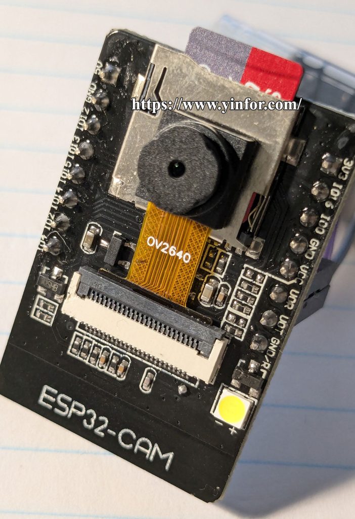
ESP32-CAM board
 $5.53 for the ESP32-CAM WiFi Module and OV2640 Camera Module.
The Specification:
Working voltage 4.75-5.25V
SPIFlash default 32Mbit
RAM internal 520KB + external 8MB PSRAM
Wi-Fi 802.11b/g/n/e/i
Bluetooth Bluetooth 4.2BR/EDR and BLE standard
Support interface (2Mbps) UART, SPI, I2C, PWM
Support TF card, maximum support 4G
IO port 9
Serial port rate default 115200bps
Spectrum range 2400 ~2483.5MHz
Antenna form Onboard PCB antenna, gain 2dBi
Image output format: JPEG (only OV2640 support), BMP, GRAYSCALE
Packaging method DIP-16
Transmit power 802.11b: 17±2dBm (@11Mbps)
802.11g: 14±2dBm (@54Mbps)
802.11n: 13±2dBm (@MCS7)
Receiving sensitivity CCK, 1Mbps: -90dBm
CCK, 11Mbps: -85dBm
6Mbps(1/2BPSK): -88dBm
54Mbps (3/464-QAM): -70dBm
MCS7 (65Mbps, 72.2Mbps): -67dBm
Power consumption Turn off the flash: 180mA@5V
Turn on the flash and adjust the brightness to the maximum: 310mA@5V
Deep-sleep: The lowest power consumption can reach 6mA@5V
Moderm-sleep: the lowest can reach 20mA@5V
Light-sleep: the lowest can reach 6.7mA@5V
Security WPA/WPA2/WPA2-Enterprise/WPS
Working temperature -20 ℃~ 70 ℃
Storage environment -40 ℃~ 125 ℃, <90%RH
The ESP32 board has an ov2640 camera. This board has no USB port. So I need an FTDI device to connect to the computer.
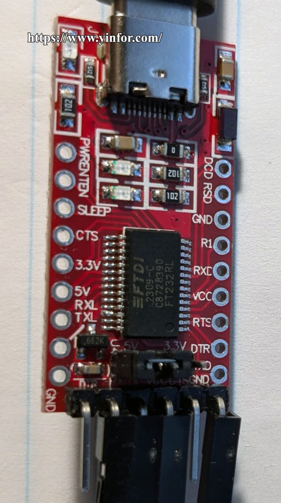
 $2 for FT232 Red Module. YP-05 is labeled on the back of the board.
Specification:
· Using FT232RL chip of FTDI;
· Lead out all signal ports of FT232RL chip, TTL/CMOS level;
·RXD/TXD transceiver communication indicator light;
·USB power supply, optional 5V or 3.3V interface level (if other levels are required, the target voltage can be supplied directly on the VCC and GND pins).
And last, I need a female-to-female Jumper Wire Dupont Cable.
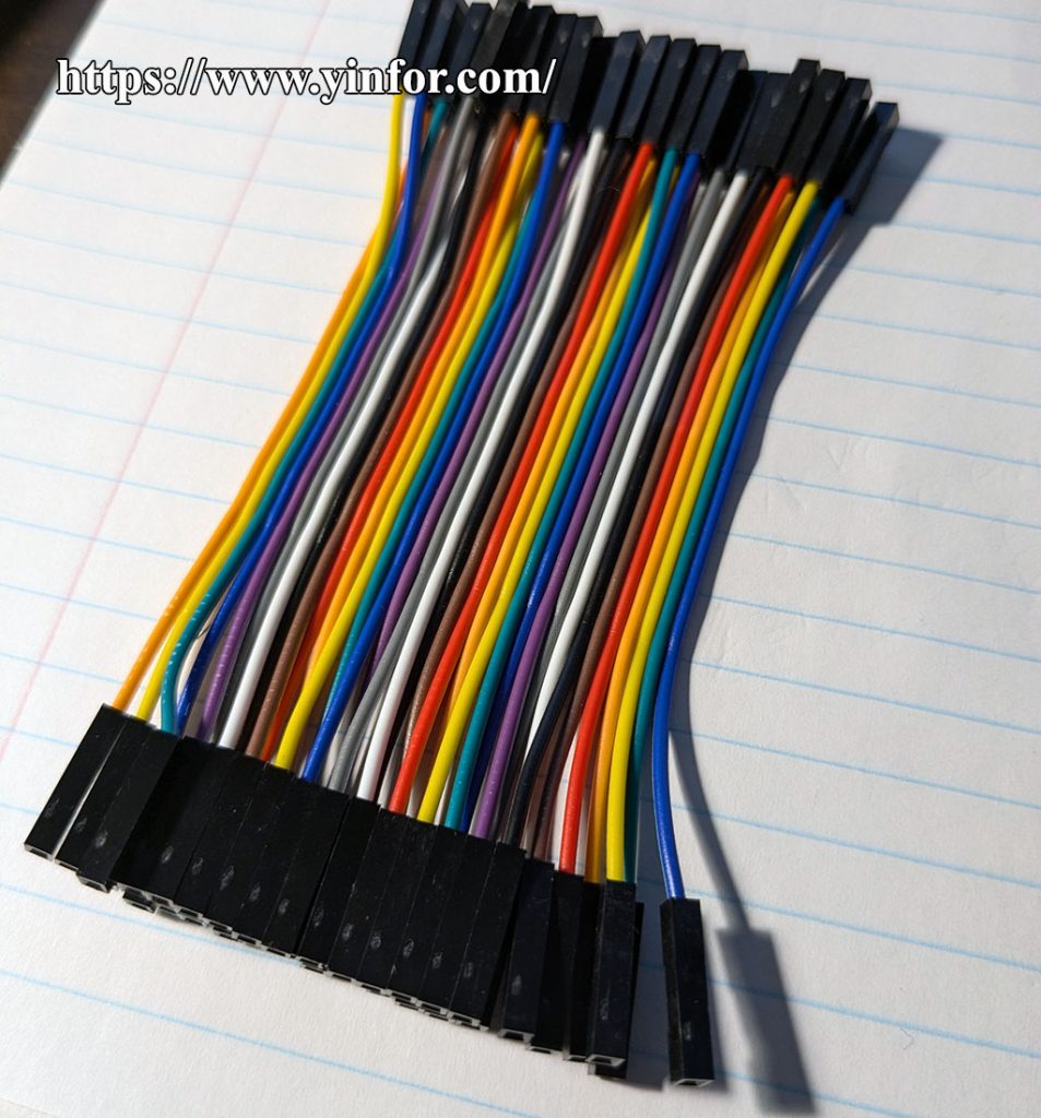 I got the 40-pin female-to-female jumper wire on Temu. $2.48
I followed the instructions on Random Nerd Tutorials.
The first step is to connect them for programming.
How to Program / Upload Code to ESP32-CAM AI-Thinker (Arduino IDE)
 It is not that hard to do it. Just make sure all the pins are the same as the article.
My stuff is as follows. The FTDI board is USB Type-C. I used a UGreen USB Type A to Type C cable to connect it. I also have a SanDisk Ultra 16GB MicroSD card plugged in for storage.
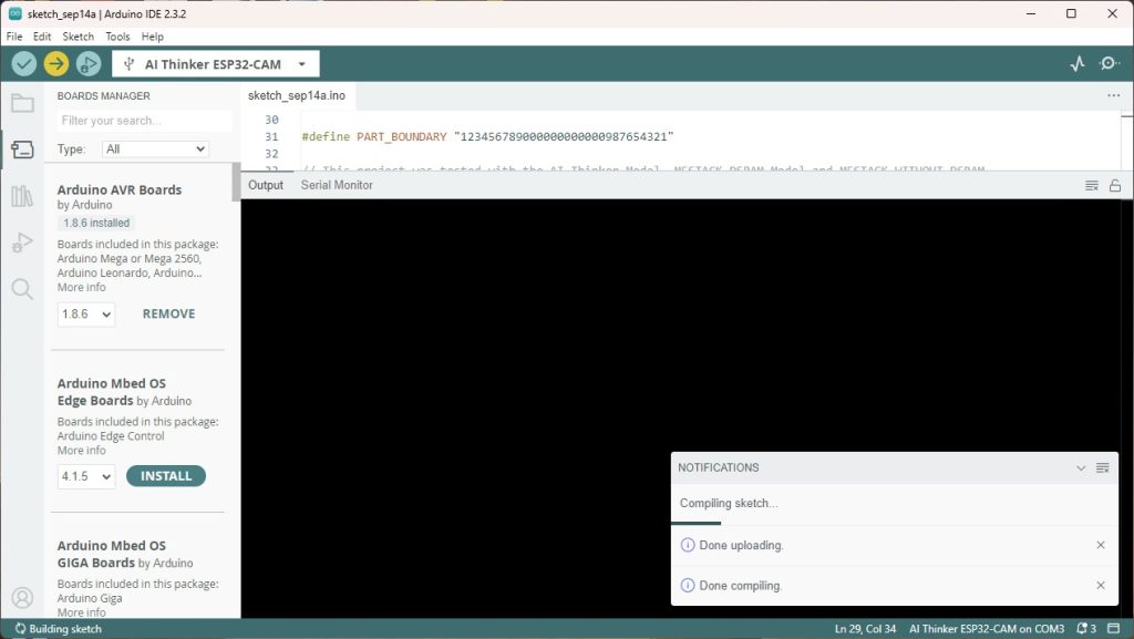
I do use Arduino IDE to program and upload it.
The first trial is to make it a camera.
ESP32-CAM take photo and save to MicroSD card.
It works. But the photo is kind of tinted or blue/green. With Flash, but no help.
The second trial is to make it a streaming web server.
ESP32-CAM Video Streaming Web Server (works with Home Assistant)
The color of the picture is OK. But the Web server is kind of slow. I have to wait for the picture to load. Just like twenty-five years ago. I dialed up to get an Internet connection with a 14.4kbps modem.
After a while, I feel the board is hot when I unplug it.
The last one I tried yesterday was a photo web server.
ESP32-CAM take photo and display in Web Server.
The slow-loading picture is still the problem. The board is also hot.
I thought the problems above are related as below:
- WiFi connection with internal antenna. (Maybe the external antenna can solve the problem)
- Processor is not strong enough?
- OV2640 camera module is hot?
- Code issue?
I have no idea. Someone said to add a heatsink. Someone said the code/program is too heavy for the ESP32.
If you know why, please leave your comment.
